|
OLE Developer Guide
Latest Git
|


|
|
OLE Developer Guide
Latest Git
|
|
The reference design is based on the PIC 32 Ethernet Starter Kit (DM320004-2) which uses a MX795F512L MCU.
The PIC32 USB Starter Kit III (DM320003-3) is cheaper and should also work. The latter uses a MX470F512L MCU so you may need to change some settings.
You'll also need an I/O breakout board: PIC32 I/O Expansion Board (DM320002)
The hardware design for the Number1 is also available to look at.
On the DM320004-2 starter kit, with the DM320002 I/O board, the pin assignments are as follows:
| Use | Pin Name | J1 Connector | J11 Connector | Port | Bit |
|---|---|---|---|---|---|
| UART RX | SCM1A/RF2 | 88 | 41 | - | - |
| UART TX | SCM1B/RF8 | 90 | 43 | F | 8 |
| TX Enable | PMPD11/RF0 | 18 | 7 | F | 0 |
| RX Enable | PMPD10/RF1 | 16 | 8 | F | 1 |
| Input Capture | IC2 | 54 | 26 | - | - |
| RDM Identify | OC4/RD3 | 40 | 18 | D | 3 |
| RDM Mute | SS1/IC2/RD9 | 52 | 23 | D | 10 |
If you use a different MCU, you can change the pin assignments in system_settings.h
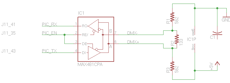
To build a basic DMX / RDM Transceiver module, you'll need:
 1.8.8
1.8.8