|
Ja Rule
Latest Git
|
|
Ja Rule
Latest Git
|
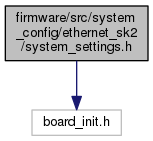
Configuration settings for the main application.
These will need to be adjusted to suit the particular processor / board used.
Go to the source code of this file.
Macros | |
Board Specific Hooks | |
These hooks can be used for board specific configuration at various stages during the initialization sequence. | |
| #define | PRE_APP_INIT_HOOK EthernetSK2_PreAppHook |
| This hook is called prior to the initialization of the application modules (APP_Initialize). More... | |
Coarse Timer | |
Settings for the Coarse Timer. These are used to initialize CoarseTimer_Settings. | |
| #define | COARSE_TIMER_ID 2 |
| The timer to use for the coarse timer. | |
Transceiver | |
Settings for the Transceiver. These are used to initialize TransceiverHardwareSettings. | |
| #define | TRANSCEIVER_UART 1 |
| The USART to use for the DMX/RDM transceiver. | |
| #define | TRANSCEIVER_TIMER 3 |
| The Timer module id to use for the DMX/RDM transceiver. | |
| #define | TRANSCEIVER_IC 2 |
| The input capture module id to use for the DMX/RDM transceiver. | |
| #define | TRANSCEIVER_PORT PORT_CHANNEL_F |
| The port to use for the direction & break pins. | |
| #define | TRANSCEIVER_PORT_BIT PORTS_BIT_POS_8 |
| The bit position of the I/O pin used to create the break. | |
| #define | TRANSCEIVER_TX_ENABLE_PORT_BIT PORTS_BIT_POS_0 |
| The bit position of the TX enable pin. | |
| #define | TRANSCEIVER_RX_ENABLE_PORT_BIT PORTS_BIT_POS_1 |
| The bit position of the RX enable pin. | |
RDM Responder | |
Settings for the RDM Responder. These are used to initialize RDMResponderSettings. | |
| #define | RDM_RESPONDER_IDENTIFY_PORT PORT_CHANNEL_D |
| The port containing the RDM identify LED. | |
| #define | RDM_RESPONDER_IDENTIFY_PORT_BIT PORTS_BIT_POS_3 |
| The bit position of the RDM identify LED. | |
| #define | RDM_RESPONDER_MUTE_PORT PORT_CHANNEL_D |
| The port containing the RDM mute status LED. | |
| #define | RDM_RESPONDER_MUTE_PORT_BIT PORTS_BIT_POS_12 |
| The bit position of the RDM mute status LED. | |
SPI DMX | |
Settings for the SPI Pixel Controller. These are used to initialize SPIRGBConfiguration. | |
| #define | SPI_MODULE_ID SPI_ID_1 |
| The SPI module to use for output. | |
| #define | SPI_BAUD_RATE 1000000u |
| The baud rate of the SPI output. | |
| #define | SPI_USE_ENHANCED_BUFFERING true |
| Use enhanced buffering. | |
USB | |
USB Configuration. | |
| #define | USB_POWER_CONSUMPTION 100 |
| The power consumption of the USB device. More... | |
| #define PRE_APP_INIT_HOOK EthernetSK2_PreAppHook |
This hook is called prior to the initialization of the application modules (APP_Initialize).
Remember that pins will default to analog if they share a function with the A/D Convertor. If any of your pins share with the ADC, you'll need to change them to digital mode. This should be done using this hook.
| #define USB_POWER_CONSUMPTION 100 |
The power consumption of the USB device.
Per the USB spec, this is multipled by 2 to give the current in mA. e.g. 50 = 100mA, 100 = 200mA
 1.8.8
1.8.8

